RECENT POSTS

Drainiac® Petroleum Filter Valves – TOG in Stormwater Test
Efficacy of Drainiac® Petroleum Filter Valves for Removing Oil from Stormwater in Secondary Containment Systems
Discharging water that contains a visible sheen is a violation of the Clean Water Act and can subject facilities to fines under the EPA’s Stormwater and Spill Control and Countermeasures Plan (SPCC) Rules. In addition to waters having no visible sheen when they are discharged, most states and municipalities have established a 5 mg/l limit on Total Oil and Grease (TOG) in Stormwater discharges.
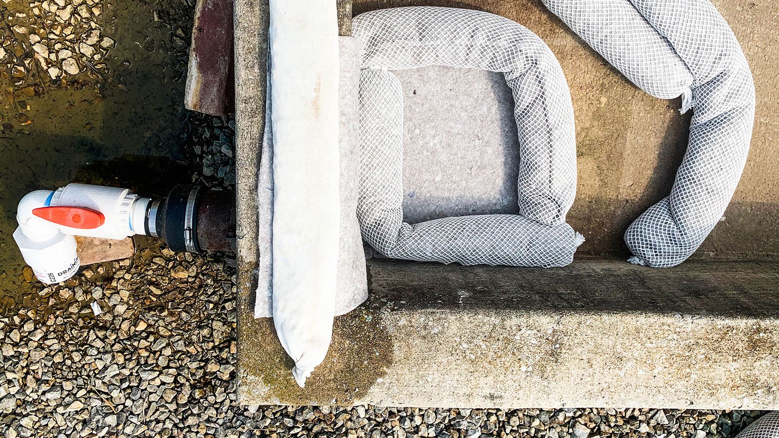
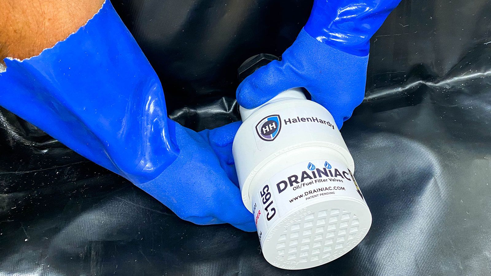
To help facilities meet these requirements, Drainiac® Petroleum Filter Valves can be connected to stormwater outflow valves on secondary containment systems. The Filter Valve is an oil-water separator that captures oil and allows clean water to flow through. As the filtering media in the unit captures oil, it swells. When the filtering media has reached capacity, the swelling of the filtering media shuts off the flow of water through the unit to prevent oil from being discharged.
To verify that the Drainiac® Petroleum Filter Valve reduces TOG in stormwater to less than 5 mg/l, an independent laboratory test was conducted by Fairway Labs in Altoona, PA. EPA method 1664A (Recommended Method for determination of oil and grease and total petroleum hydrocarbons in wastewater) was used to determine the presence of TOG in the water samples.
The following protocol was developed to simulate how the Drainiac® Petroleum Filter Valve would be used in the field, producing the water samples sent for analysis.
Test Procedure
To demonstrate the consistency of Drainiac® Petroleum Filter Valves, two identical tests are performed using two separate 6” Drainiac® Petroleum Filter Valves.
For each test, the Drainiac® Petroleum Filter Valve is attached to a water collection vessel so that constant head pressure can be maintained through the filter valve.
Step 1: Produce clean water control samples
- Calibrate water inflow to the collection vessel and regulate to maintain 6” of constant head pressure, producing a 6.5 gallon/minute outflow rate.
- After two minutes of steady flow at 6” of head pressure, collect a grab sample of water outflow from the Filter Valve.
Step 2: Introduction of 100 ml of dielectric fluid (DF)
- After two minutes of water flowing through the Drainiac® Petroleum Filter Valve, introduce 100 ml of DF to the water collection vessel, then shut off water flow.
- Allow DF to penetrate the Filter Valve for five minutes, then collect a grab sample of water outflow from the Filter Valve.
Step 3: Recalibrate water inflow and introduce an additional 200 ml F
- Recalibrate water inflow to the collection vessel to match outflow of 4.2 gallons per minute.
- After two minutes of steady flow, introduce 200 ml DF (300 ml cumulative DF) to the collection vessel, then shut off water flow.
- Allow DF to penetrate the Filter Valve for five minutes, then collect a grab sample of water outflow from the Filter Valve.
Step 4: Recalculate water inflow and introduce an additional 300 ml DF
- Recalibrate water inflow to the collection vessel to match outflow of 3.1 gallons per minute.
- After two minutes of steady flow, introduce 300 ml DF (600 ml cumulative DF) to the collection vessel, then shut off water flow.
-
After three minutes, collect grab sample of water outflow from the Filter Valve
Note: sample is taken after three minutes in order to capture enough water for the sample. Due to the swelling of the Drainiac® Polymers, water flow will be very slow.
Step 5: Confirm stop of water flow through Filter Valve
-
Add 6” of water to the collection vessel.
-
Monitor for six minutes to confirm that all flow through the Filter Valve has stopped.
Test Results
EPA Method 1664A ( (Recommended Method for Determination of Oil and Grease and Total Petroleum Hydrocarbons in Wastewater) was used to determine the presence of DF in the water samples.
- No hydrocarbons were detected in the control samples of water.
- All subsequent samples reported less than 5 mg/L of hydrocarbons.
The Fairway Laboratory Report dated 11/13/19 follows this summary.
- M2C-2 samples were from the first Drainiac® Petroleum Filter Valve
- M2C-3 samples were from the second Drainiac® Petroleum Filter Valve
Learn More About Drainiac®
Related Articles
Subscribe for Updates:
Sign up here to get the latest news, rules, and regulations and delivered right to your inbox.

